Loading…
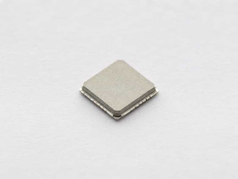
QFN-56 · RP2040
ActiveDual Cortex-M0+ MCU
RP2040
Raspberry Pi · QFN-56 · Dual Cortex-M0+ MCU
Price on Request
Get a competitive quote within 24 hours. Volume discounts available. Shenzhen stock ships in 1-2 business days.
Overview
The RP2040 is Raspberry Pi's own microcontroller: two Arm Cortex-M0+ cores running at up to 133 MHz (and 200 MHz at 1.15 V core if you push it), 264 KB of on-chip SRAM split across six independent banks, and no internal program memory. Code lives in an external QSPI flash that the chip executes in place from, up to 16 MB, over six dedicated flash pins with an XIP cache. That architectural choice is the key BOM decision for any RP2040 board - you must source a serial NOR flash (W25Q32JV, W25Q64JV and similar) alongside the MCU, and flash price swings directly affect your landed cost.
The rest of the feature set is deliberately flexible: 30 multifunction GPIO (four of them analogue), two UARTs, two SPI controllers, two I2C controllers, 16 PWM channels, a USB 1.1 host/device controller with PHY, a 4-channel 12-bit ADC sampling at 500 ksps with an internal temperature sensor, a DMA controller, two PLLs, an on-chip programmable LDO for the 1.1 V core, and the headline feature - eight PIO state machines across two PIO blocks. PIO lets you implement interfaces the fixed peripherals lack (WS2812 timing, quadrature encoders, VGA and DVI output, custom serial protocols) in hardware-timed assembly while the cores do something else. Supply is 1.8 V to 3.3 V nominal on IOVDD with 3.63 V absolute maximum, and the package is a 7 x 7 mm QFN-56 at 0.4 mm pitch with a smaller-than-standard exposed pad, which requires a purpose-built footprint.
Sourcing notes: Raspberry Pi sells RP2040 through authorised distributors in tape and reel, and the chip has been broadly available since launch, but the open popularity produced a grey market of re-marked and second-hand parts. Verification is straightforward - every RP2040 carries a unique 64-bit board ID in flash and responds to the USB boot (BOOTSEL) path, so you can identify a dead or fake part by attempting a UF2 drag-and-drop boot and reading the flash ID with picotool. Also inspect QFN pad wetting and laser marking. Beware parts damaged by improper reflow: the QFN-56 with reduced ePad needs a controlled profile and via-stitched ground pad. Typical MOQ is one reel or 100 pcs on cut tape, with 1-3 day dispatch from Shenzhen stock.
Key Features
- Dual Arm Cortex-M0+ cores at up to 133 MHz with 264 KB SRAM in six banks
- Eight PIO state machines for hardware-timed custom interfaces (WS2812, VGA, encoders)
- Execute-in-place QSPI interface supporting up to 16 MB external flash - no on-chip program memory
- 30 GPIO, 4-channel 12-bit ADC at 500 ksps, USB 1.1 host/device, 16 PWM channels
- QFN-56 7 x 7 mm, 0.4 mm pitch with a reduced exposed pad requiring a custom footprint
Typical Applications
- Raspberry Pi Pico-class dev boards and low-cost embedded controllers
- Custom keyboards, MIDI controllers and HID devices over native USB
- LED matrix, pixel-strip and small display drivers using PIO timing
- Sensor hubs, dataloggers and motor control with quadrature feedback
- OEM replacement for STM32F0/F1-class designs needing more RAM and cheaper silicon
Specifications
- Core
- Dual ARM Cortex-M0+
- Max Clock
- 133 MHz
- SRAM
- 264 KB
- Program Memory
- None on-chip; external QSPI flash (XIP) up to 16 MB
- Supply Voltage (IOVDD)
- 1.8 to 3.3 V
- GPIO
- 30
- ADC
- 4-channel, 12-bit, 500 ksps
- PIO
- 8 Programmable State Machines (2 x PIO)
- Pins
- 56
- RoHS
- Compliant
Procurement Tips
Quote the flash memory on the same BOM line as the RP2040 and validate the pair together - most RP2040 production failures we see are XIP or QSPI timing issues caused by mixing chip vendors or using a flash part outside the tested speed grade.
Frequently Asked Questions
Does the RP2040 include flash memory?
No. It boots from external QSPI NOR flash and executes in place from it. Your BOM must include a flash device (typically 2-16 MB such as W25Q32JV or W25Q64JV) on the six dedicated QSPI pins. This is the single biggest difference from an STM32 or ATmega, where flash is on-die.
How does the RP2040 compare with an STM32F103 or ESP32?
Against the STM32F103C8T6 the RP2040 has far more RAM (264 KB versus 20 KB), dual cores, USB and PIO, but no CAN and a 12-bit ADC without DMA-triggered dual-ADC tricks. Against the ESP32-WROOM-32 it has no Wi-Fi or Bluetooth at all - if you need radio, pair RP2040 with a Wi-Fi module or use a Pico W board. Choose RP2040 for compute-per-dollar and flexible I/O, ESP32 for connectivity.
What power supplies does an RP2040 design need?
IOVDD is nominally 1.8 V to 3.3 V (3.63 V absolute maximum) and supplies the GPIO, USB PHY, ADC and the on-chip regulator input. The internal LDO generates DVDD at about 1.1 V for the core; connect VREG_VOUT to DVDD externally with 100 nF decoupling per pin, or drive DVDD from your own efficient regulator for low-power designs. On a Pico-style board an external buck-boost converts a 1.8-5.5 V VSYS input down to 3.3 V.
Can I overclock the RP2040?
Yes. The datasheet documents operation up to 200 MHz with a 1.15 V core supply, and hobby boards routinely run 150-250 MHz at stock voltage. Overclocking is not a warranted specification, so validate timing margin, flash quad-SPI speed and temperature rise before committing it to a production design.
How do I verify that RP2040 chips are genuine and not re-marked or reflow-damaged?
Hold BOOTSEL while connecting USB: a good chip enumerates as an RP2 Boot mass-storage device, which proves the ROM bootloader, USB PHY and flash path all work. Then flash a UF2 test image and read the unique flash ID and board ID with picotool. Re-marked or dead parts fail to enumerate; reflow-damaged parts often enumerate but fail QSPI writes at speed. Physically check pad wetting under magnification and confirm laser marking.
What is the MOQ and lead time for RP2040?
Raspberry Pi ships in tape and reel; we supply 100 pcs on cut tape for prototyping and full reels for production. Authorised channel lead time is normally short, but allocation spikes have occurred during high-demand periods. Our Shenzhen stock typically dispatches in 1-3 business days for quantities up to 20,000 pcs.
Alternatives & Equivalents
View full cross-reference table →Need RP2040 pricing and availability?
Submit an RFQ — we reply within 24 hours with stock, pricing, lead time and packaging options.
Request a Quote →