Loading…
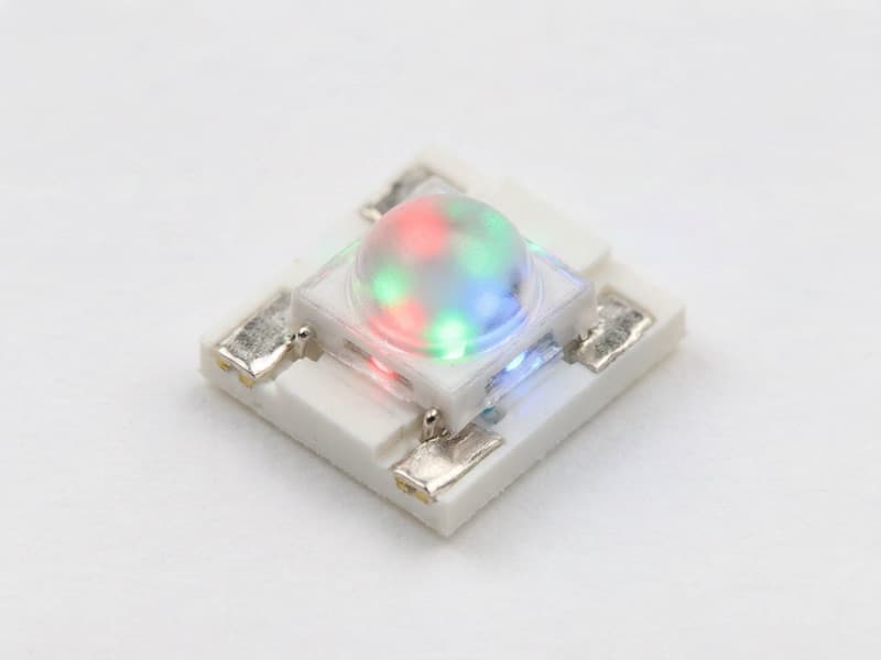
5050 SMD · WS2812B
ActiveAddressable RGB LED (NeoPixel-compatible)
WS2812B
Worldsemi · 5050 SMD · Addressable RGB LED (NeoPixel-compatible)
Price on Request
Get a competitive quote within 24 hours. Volume discounts available. Shenzhen stock ships in 1-2 business days.
Overview
The WS2812B is Worldsemi's intelligent control LED integrated light source: a 5050 SMD package that contains three RGB emitter dies, a constant-current driver and a complete serial control IC, forming one independently addressable pixel. The package has four pins — VDD, DOUT, VSS and DIN — and the control circuit and the LEDs share the single power source. Data arrives on one wire in a non-return-to-zero protocol at 800 kbps: each pixel captures its own 24 bits (eight per colour, in green-red-blue order with the most significant bit first), latches them, then reshapes and forwards the remaining bits to the next device through DOUT. Because the signal is regenerated rather than passed through, waveform distortion does not accumulate, and Worldsemi specifies cascades of at least 1024 pixels at a 30 fps refresh rate, with reliable transmission between any two points more than 5 m apart without extra buffering. Transmission delay from DIN to DOUT is 300 ns maximum at 15 pF.
Timing is the specification that determines whether your driver works. The bit period is 1.25 µs with a ±600 ns window. In the January 2016 V1.0 datasheet, T0H is 0.4 µs ±150 ns and T0L is 0.85 µs ±150 ns for a zero bit, T1H is 0.85 µs ±150 ns and T1L is 0.4 µs ±150 ns for a one bit, and the reset code is a low period above 50 µs. The earlier 2013 revision quotes T1H at 0.8 µs and T1L at 0.45 µs, and the WS2812B-V5 revision tightens the window further. A driver generating roughly 0.4 µs and 0.85 µs pulses satisfies all of these, but software delay loops on a variable-clock MCU often do not; use a hardware peripheral instead — SPI at 6.4 MHz or 8 MHz, the ESP32 RMT peripheral, the RP2040 PIO, or a timer with DMA.
Electrically, VDD has an absolute maximum range of 3.5 V to 5.3 V and the characteristics are specified at 4.5 V to 5.5 V, so this is a 5 V part: a 3.3 V rail will not reliably light it. Input thresholds are VIH = 0.7 × VDD and VIL = 0.3 × VDD with 0.35 V of hysteresis and ±1 µA of input current, which means a 3.3 V controller cannot meet VIH at VDD = 5 V (3.5 V is required) — add a level shifter or a sacrificial first pixel powered at 4.3 V. Optical data: red at 620 nm to 630 nm with 550 mcd to 700 mcd and a forward voltage of 1.8 V to 2.2 V, green at 515 nm to 530 nm with 1100 mcd to 1400 mcd and 3.0 V to 3.2 V, blue at 465 nm to 475 nm with 200 mcd to 400 mcd and 3.0 V to 3.4 V. The datasheet does not state the drive current because the internal constant-current circuit sets it; measured values are around 14.7 mA red, 14.1 mA green and 14.3 mA blue, so roughly 43 mA at full white. For conservative power design budget 60 mA per pixel. Intelligent reverse-connection protection means a reversed supply will not damage the control IC, and scan frequency is not less than 400 Hz so no visible flicker appears on camera.
Design and sourcing guidance: decouple every pixel with a 100 nF ceramic between VDD and VSS as close to the package as possible, add a 300 ohm to 500 ohm series resistor on the first DIN, and inject power into the strip every 1 m to 2 m because the copper traces cannot carry 60 mA per pixel over long runs. Watch the current budget — a 300-pixel strip at full white draws about 18 A. Counterfeit and variant risk is very high: parts sold as WS2812B are frequently WS2811-plus-separate-LED assemblies, older WS2812 dies with wider timing tolerance, WS2812B-V5 parts with different timing, or lower-brightness bins. Verify by measuring full-white current per pixel, checking green brightness against the 1100 mcd to 1400 mcd specification, and confirming the reset threshold. MOQ is typically one reel of 1000 pcs for the bare LED, with strips and modules in shorter lengths. Shenzhen stock ships same-day.
Key Features
- One-wire addressable RGB pixel with integrated control IC and constant-current driver
- 800 kbps NRZ protocol, 24-bit GRB data, at least 1024 pixels cascaded
- 5050 SMD-4 package: VDD, DOUT, VSS, DIN — no external components per pixel
- Signal is reshaped at every pixel, so cascade length is not limited by distortion
- Intelligent reverse-connection protection for the control IC
Typical Applications
- Architectural and decorative LED strips, cove lighting and signage
- Full-colour video panels and irregular indoor or outdoor screens
- Consumer products with status and notification lighting
- Stage, DJ and event lighting fixtures
- Gaming peripherals, PC cases and keyboard backlighting
- Prototypes and interactive installations on ESP32, RP2040 and AVR platforms
Specifications
- Device Type
- Addressable RGB LED with Integrated Control IC
- Supply Voltage (VDD)
- 3.5 to 5.3 V
- Data Interface
- Single-Wire NRZ, 800 kbps (DIN / DOUT)
- Colour Resolution
- 24-bit (8 Bits per Colour, 16777216 Colours)
- Data Format
- GRB Order, High Bit First
- Current per Colour at Full White (Typ, 5 V)
- 14 to 18 mA
- Luminous Intensity (Red / Green / Blue)
- 550-700 / 1100-1400 / 200-400 mcd
- Reset (RES) Low Time
- > 50 µs
- Pins
- 4
- RoHS
- Compliant
Procurement Tips
Buy the WS2812B as a matched bin and ask for the brightness and colour-consistency data, because mixed bins show visible banding in long strips. For production designs, specify either a hardware driver peripheral or a level shifter on the DIN line and confirm which revision (standard or V5) you are receiving, since timing tolerance differs between them.
Frequently Asked Questions
WS2812B versus WS2811, WS2812B-V5 and SK6812 — what is the difference?
The WS2811 is a separate three-channel constant-current controller IC that drives external LEDs and usually runs at 12 V or 24 V, so it is the choice for long runs and high-power fixtures. The WS2812B integrates controller and RGB dies in one 5050 package at 5 V. The WS2812B-V5 is a later revision with tighter timing and lower quiescent current, and its bit window differs enough that marginal software timing fails on it. The SK6812 from another vendor is pin- and protocol-compatible with a slightly different timing spec and often better colour consistency. For a new design on a 5 V rail with a hardware peripheral driver, WS2812B or SK6812 are both safe.
Why do my WS2812B pixels flicker or latch the wrong colours with a 3.3 V microcontroller?
Two separate problems. First, VIH is 0.7 × VDD, so at VDD = 5 V the pixel needs 3.5 V on DIN — a 3.3 V output is below threshold and marginal. Use a level shifter (74HCT125 powered at 5 V works well), or power the first pixel from 4.3 V and feed its DOUT to the rest. Second, software delay loops drift with compiler optimisation, interrupts and clock scaling. Use SPI at 6.4 MHz or 8 MHz, the ESP32 RMT peripheral, RP2040 PIO, or a timer with DMA, and disable interrupts during bit-banging if you must.
How much current do I need to budget?
Measured full-white current is about 14.7 mA red, 14.1 mA green and 14.3 mA blue per pixel, roughly 43 mA total, but the standard engineering budget is 60 mA per pixel at 5 V to cover worst-case bins and full brightness. A 300-pixel strip at maximum white therefore draws around 18 A and needs a properly sized supply and heavy power injection. In practice most animations average far less; limit brightness in firmware to 20 to 30 percent and your supply requirement drops by more than half.
How long can a data run be, and do I need to re-drive the signal?
Worldsemi specifies reliable transmission between any two points more than 5 m apart without any additional circuit, because each pixel reshapes and amplifies the signal before forwarding it. That is per hop, so total chain length is limited by refresh rate, not by distance: at 30 fps you can cascade at least 1024 pixels. Beyond that, or where the cable is noisy, insert a spare pixel as a repeater or use a differential line driver. Keep the data line away from motor and switching-node wiring, and terminate the far end with the strip's own last pixel.
What is the colour order, and why does my strip show green where I set red?
The WS2812B transmits 24 bits in green-red-blue order with the most significant bit of each byte first. If you send RGB data you will get swapped colours. Most libraries handle this, but raw SPI or DMA drivers need the byte order set explicitly. Some clones and the SK6812 RGBW variant use a different order or add a fourth white byte, so check the datasheet of the exact part on your strip before writing a bare-metal driver.
Do I need a reset pulse between frames?
Yes. The reset code is a low period above 50 µs on DIN, which latches the received data and prepares the pixel for the next frame. Without it the first pixel keeps consuming bits and the data does not propagate correctly. Most drivers send 50 µs to 300 µs of low between frames; longer is safe. Note that the pixel latches on the reset, so the update is not visible until the reset edge is generated.
How do I detect counterfeit or mis-binned WS2812B?
Measure three things on a sample. Full-white current per pixel should be around 40 mA to 60 mA at 5 V; parts drawing 20 mA are usually lower-current clones and will look dim. Check green luminous intensity against the 1100 mcd to 1400 mcd specification with a light meter, since green dominates perceived brightness. And verify the timing tolerance by driving at the edge of the spec window — genuine Worldsemi parts hold ±150 ns, clones often fail. Also inspect the moulded marking and the 5050 package dimensions. We test brightness and current bin consistency on every reel.
What is the MOQ and lead time?
MOQ is one reel of 1000 pcs for the bare WS2812B 5050 LED, or shorter quantities for assembled strips and breakout boards (typically 1 m, 5 m or 300-pixel reels). Shenzhen stock is very deep and ships same-day or next-day; Worldsemi authorized-channel lead time is four to eight weeks. For high-volume strip production, specify the waterproof rating (IP20, IP65, IP67) and the copper weight of the strip separately, since those drive cost more than the LED itself.
Alternatives & Equivalents
View full cross-reference table →Need WS2812B pricing and availability?
Submit an RFQ — we reply within 24 hours with stock, pricing, lead time and packaging options.
Request a Quote →